Voltmeters are used to measure. Individual circuit components are represented using circuit symbols. Web the main difference between ammeter and voltmeter is that ammeter comes in handy to measure the flow of current.
Simple Circuit Diagram Gone Ammeter And Voltmeter Wiring Diagrams Nea
Web 3 answers sorted by:
Web Learning Objectives By The End Of This Section, You Will Be Able To:
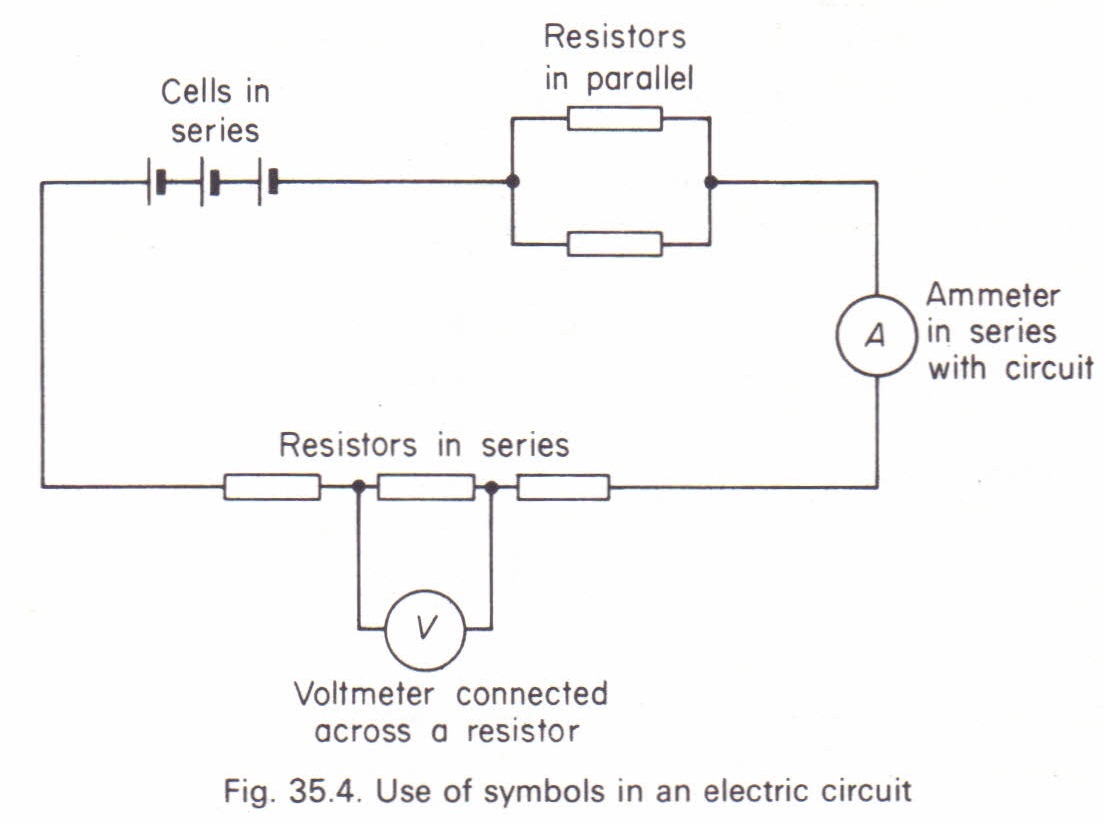
Web 1 2 3 4 5 6 7 8 measuring current and voltage you need to know how to measure the current that flows through a component in a circuit and the voltage across it. The ideal resistance of an ammeter. 3 an easy way to see it might be this:
It Is Connected In Parallel Across The Points In The Circuit.
Web don’t worry, they are the same thing. I guess if you connect your voltmeter wrong, you'll just get bad readings. A multimeter is a similar device.
Draw A Diagram Showing An Ammeter.
Explain why a voltmeter must be connected in parallel with the circuit. When certain resistance is connected in parallel to voltmeter, reading of ammeter increases three. Web a voltmeter is a device which is used to measure voltage in an electric circuit.
On The Other Hand, The Voltmeter Comes In Handy For.
Web a voltmeter and an ammeter are connected in series across an ideal cell. Ammeters can be easily damaged! Web the current flowing through a component in a circuit is measured using an ammeter;
It Is Present In Both Digital And Analogue Forms.
Ammeters are used to measure the current flowing through components. Web ammeters measure the amount of current in a circuit, while voltmeters measure the potential difference or voltage between two points in a circuit. You can measure current and other things with a multimeter.
In This Article, We Will.
Needs to measure a potential difference, so you need to hook its ends to the two points which. Series “multiplier” resistors are used to give voltmeter. The ammeter must be connected in series with the component.
To Measure The Voltage Across The.